Filtration Systems
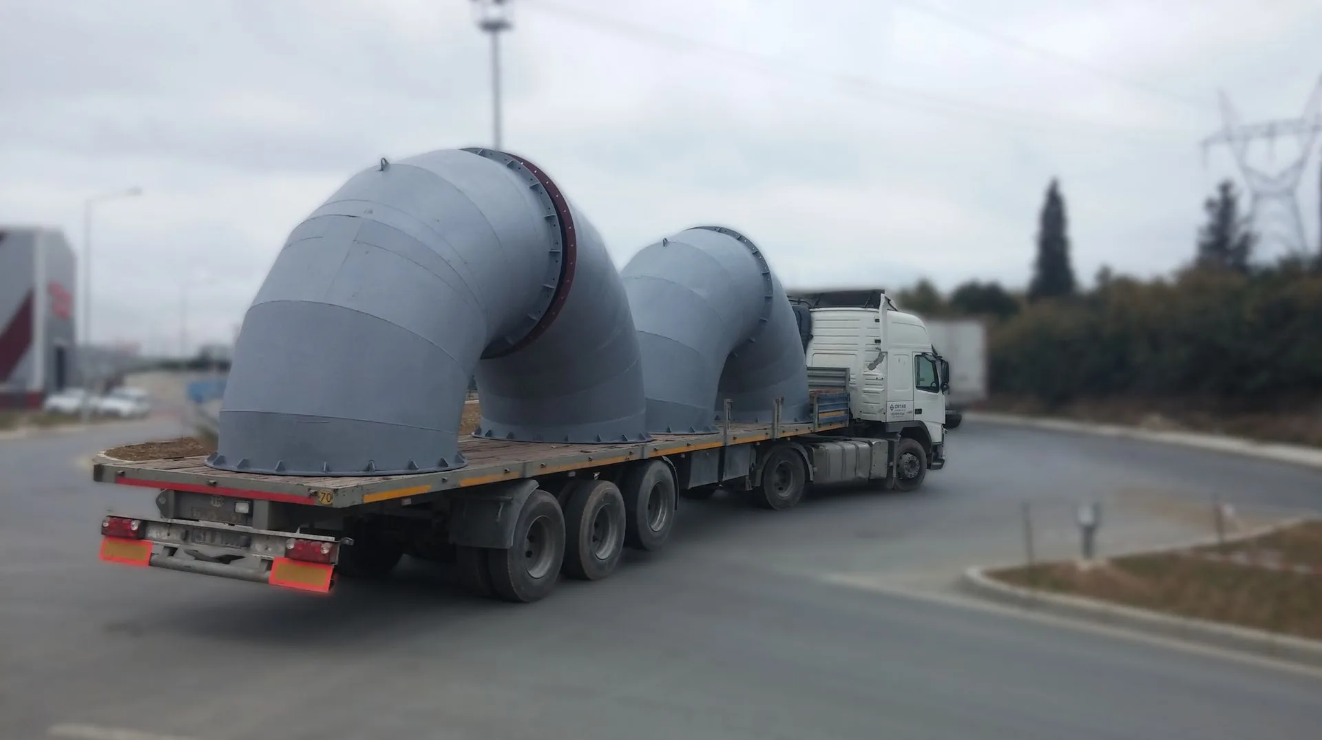
Industrial elbows are used at directional change points in filtration and gas duct systems of steel plants and energy facilities. DNL Mühendislik standard manufacturing range is 5 to 7 meters in diameter. Larger diameters can be produced per customer project. Material options include carbon steel (CS), stainless steel (SS), boiler plate, and corten steel. Material selection is determined by the customer's process conditions and gas chemistry.
No. There are two separate elbows in the same gas path, and they're constantly confused. The distinguishing question isn't "is it water-cooled": it's whether it sits on the furnace roof or in the duct line after the gas has been cooled.
The fourth-hole elbow sits on top of the furnace roof. The gas there is 1,500–1,600°C during intense oxygen lancing; water cooling is mandatory for that reason.
The industrial elbow sits downstream, in the stage after the gas is cooled. There, the gas has been dropped below 250°C to exclude dioxin formation, and a metal duct can run up to 538°C — so temperature isn't the governing constraint. What governs is cross-section, wall thickness, pressure loss, and erosion. In the stage before cooling, the gas is far hotter; that's the domain of water-cooled ducts.
Scale differs too: EAF dedusting lines run flows on the order of 1–2 million Nm³/h, which means duct diameters measured in meters.
Toulouevski & Zinurov 2013; EU JRC BREF 2013; EPA 2002
Elbow radius is a design decision that comes back as a bill — and it usually goes unnoticed.
EPA's worked example shows this clearly: the entire 76-meter straight run of duct loses 77.9 Pa, while the five elbows on the same line lose 81.7 Pa. The elbows lose more than the entire straight run. What sets the loss is the radius-to-diameter ratio.
| R/D | Loss coefficient |
|---|---|
| 0.50 | 0.80 |
| 1.00 | 0.35 |
| 1.50 | 0.27 – 0.39 |
| 2.00 | 0.24 – 0.27 |
| 2.50 | 0.22 – 0.24 |
Raising R/D from 0.50 to 1.50 eliminates more than half the loss. Past 1.50, the gains taper off quickly. The energy payoff: at a 1-million-Nm³/h plant, 0.5 kPa of additional loss adds roughly 200 kW to the induced-draft fans.
EPA 2002; EU JRC BREF 2013
We cover this on the site'sgas ducts page as well.
Three things: velocity, impact angle, and particle size. The strongest is velocity.
In full-scale plant measurements, elbow life drops with roughly the 4.5th power of velocity — so cutting velocity by 20% extends life by roughly 2.7×. But velocity can't be lowered freely: below conveying velocity, dust settles in the duct. There's a narrow window between settling and erosion, and design is about finding it.
Hardening doesn't help, and that's been measured: heat treatment hasn't improved erosion resistance in steels, and in pure metals resistance comes out inversely proportional to hardness. Erosion resistance can't be bought with material hardness.
The real question isn't "does the elbow erode," it's which stage of the line it's in. Coarse splash settles out in the settling chamber and cyclones; the downstream duct carries mostly fine fume, and fine dust's abrasiveness is disputed in the literature. Giving both stages the same wall thickness makes one needlessly expensive and the other short-lived.
Ruff 1980; Tong 1981; Toulouevski & Zinurov 2013; EU JRC BREF 2013
DNL manufactures the industrial elbow from plate such as boiler plate, cutting it into straight gores and welding them to approximate the curve; the standard range is 5 to 7 meters in diameter, with larger diameters per customer project. The number of gores depends on angle, and the rule is explicit.
| Elbow angle | Number of gores |
|---|---|
| 0 – 35° | 2 |
| 36 – 71° | 3 |
| 72 – 90° | 5 |
Above 90°, one gore is added for every extra 18°. EPA's own cost reference describes a 90° sheet-metal elbow as five-piece — that's the reference practice at large diameter.
There's one more construction preference for lines under suction: at negative pressure, welded duct is preferred over spiral-wound duct. Since an EAF dedusting line runs under suction, this applies directly.
EPA 2002
A duct lengthens as it heats, and that movement concentrates at elbows — a change of direction is the line's point of freedom.
The scale is surprising: a straight 40-meter run heating from 20°C to 250°C elongates by roughly 120 mm. From Eurocode's relation for carbon steel:
| Temperature | Elongation |
|---|---|
| 150°C | 1.65 mm/m |
| 250°C | 3.01 mm/m |
| 550°C | 7.57 mm/m |
This isn't a movement an elbow connection between two anchored ends can absorb; it's absorbed by an expansion compensator. Fabric compensator temperature classes: silicone-fiberglass or aramid ≈260°C, coated fiberglass ≈538°C. Supports must allow both axial and lateral movement.
The design temperature is chosen not for normal operation, but for the fault condition where cooling fails.
EN 1993-1-2; EPA 2002
You can calculate how much your own line will elongate with thethermal expansion calculator, and see suitable solutions on the compensator page.
Sources