Dedusting Systems
Water-cooled duct systems for high-temperature process gases — custom geometry and plant integration. Construction is tube-to-tube: tubes laid side by side and welded directly to each other.
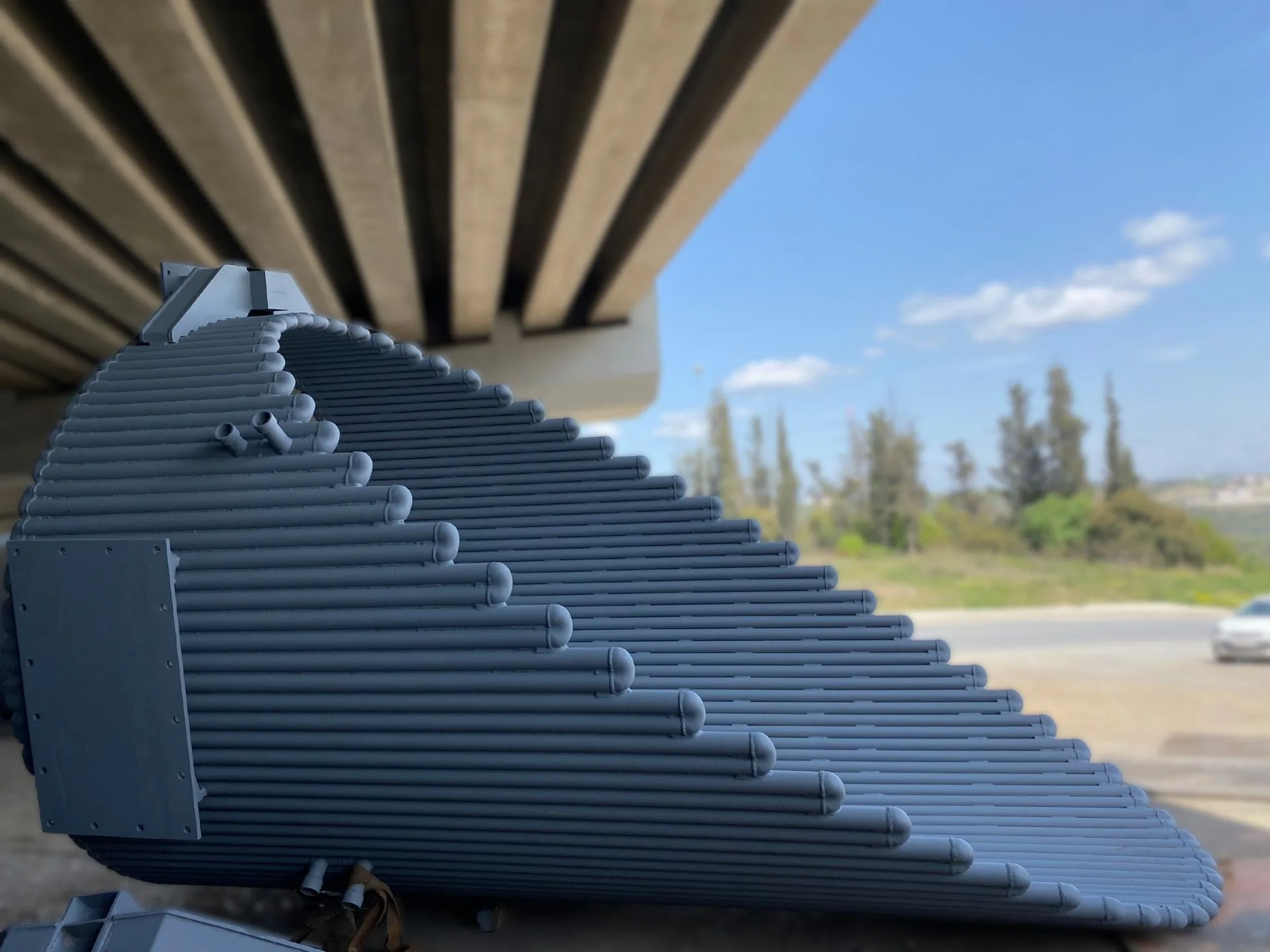
| Water-cooled high-temperature steel design |
| Custom duct geometry to client plant layout |
Tube-to-tube construction: tubes are laid side by side and welded directly to each other. Duct geometry is set on a project basis according to plant layout and gas flow.
By dividing the volumetric flow by the conveying velocity. EPA's Air Pollution Control Cost Manual gives minimum conveying velocities by dust type: 10.2 m/s for gases and very fine light dusts, 15.2 m/s for fine dry dusts, 17.8 m/s for average industrial dusts, and 20.3–22.9 m/s for coarse dusts. Too low a velocity lets dust settle in the duct; too high raises pressure loss and fan power unnecessarily.
From the measured water flow, the temperature difference between inlet and outlet, and the surface area. DNL Mühendislik'spanel cooling calculator performs this calculation and returns the result in kW/m². Cooling continues along the line: ahead of the baghouse filter, the gas is cooled in a gas cooler.
A round cross-section resists collapse, conveys dust better, and uses less metal than a square, rectangular or flattened oval section of equivalent area. This is why the EPA manual favors round ducts in air pollution control systems.
According to the EPA manual, supports should be placed every 2.5–3 meters; ducts larger than 90 cm in diameter are carried on two hangers, one on each side of the duct. On long runs, supports are designed to allow for axial and longitudinal expansion.