Continuous Casting Equipment
Copper mould tube assembly for continuous casting — a complete cooling assembly built around a square-section copper mould tube: water jacket, carrying body, and oscillation-table fittings.
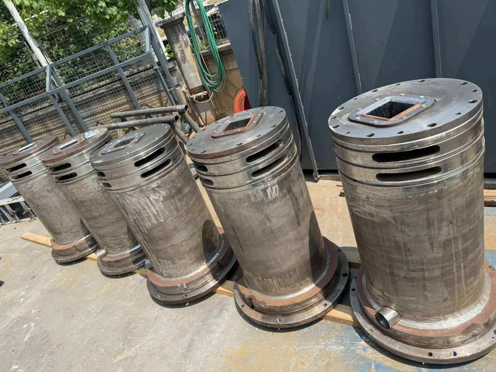
In the industry this assembly is also known as a mould assembly, billet mould, tube mould, crystallizer, or copper mould tube assembly.
A copper mould and the copper panel in an electric arc furnace are made of the same metal and do opposite jobs.
The panel protects itself from the heat arriving at it; cooling is its survival method. The peak heat flux it sees is on the order of 600–700 kW/m². In a continuous casting mould, cooling is the point itself: heat is pulled from the liquid steel to form the billet's first shell right there. Average heat flux is 2.4 MW/m², with a peak of 5.0–5.7 MW/m² — and that peak occurs just 20–50 mm below the meniscus.
There's an eightfold difference between the panel's maximum and the mould's peak. Same metal, opposite purpose.
A mould assembly is a cooling cartridge built around the copper tube inside which the billet solidifies.
The structure consists of: a square-section copper mould tube, the stainless water jacket surrounding it, the outer body carrying the water, and the flanges that carry the assembly on the oscillation table. The jacket is divided into inlet and return chambers by a ring-shaped flange plate. Top and bottom cover plates center the tube and carry ring seals around it; keys seated in channels at the tube's upper end hold the tube suspended. The outer flange seats on the mould table and is secured by clamps pressing down on it. In published field examples, mould length ranges from 705–1000 mm.
What decides a purchase: the copper tube is a consumable; the rest of the assembly is an investment item used for years. When comparing quotes, what matters is whether the flange bolt circle, seating surface, and water connections match the existing oscillation table.
US 4224977; US 4658884
The copper tube is a wear part; the assembly around it isn't discarded — it's stripped down and rebuilt at every tube change.
Published life figures spread across a wide range depending on steel grade and plant. A 1984 patent gives "at most 150 heats" for the tube of that era; another from 1999 gives a typical replacement interval of 120–200 casts. In a copper mould manufacturer's field report, conventional CuCrZr tubes were stripped at an average of 1,050 casts, while a silver-bearing copper tube at 127×127 mm ran to 1,795 casts and roughly 50,000 tons.
What ends the tube's life usually isn't wear itself — it's loss of taper: as the tube wears, the inner profile flattens, raising the risk of shape defects and breakouts. The budgeting consequence is clear: the assembly is budgeted once; the tube is budgeted separately for every campaign.
US 4658884; CA 2383075; KME field report
The jacket doesn't set how much heat is pulled from the mould; it determines whether the copper can run safely under that heat.
The breakdown of heat-transfer resistances makes this clear: the gas gap carries 420 and the cast-slag film 50 units of resistance, while the copper wall carries 2.6 and the water boundary layer only 4.3 (×10⁻⁵ m²K/W). The level of heat flux is set at the steel-to-copper interface, not on the water side. A numerical study lands in the same place: narrowing the water gap from 5 mm to 3 mm changes average heat flux by under 1%; raising water velocity from 8 to 20 m/s changes it by 3.14%.
The jacket's job is therefore less about pulling more heat and more about establishing the water velocity needed to prevent boiling and distributing water evenly around the perimeter. Typical water velocity in billet moulds is 5–10 m/s, and the gap is sized as the cross-section that establishes this velocity at the flow the plant can deliver.
After the mould, the billet continues to cool in secondary cooling, covered on thespray nozzles page.
Schwerdtfeger, 2003; Wang et al., 2023
The known failure mode of mould cooling is boiling on the cold face, and its consequence shows up directly in the billet.
A peer-reviewed study links intermittent boiling in the water channel to rhomboidity, longitudinal corner cracks, and sub-mould leaks. The mechanism: boiling doesn't occur on all faces of the mould at once, so cooling becomes asymmetric. The study's own conclusion is direct — preventing intermittent boiling is the key to producing defect-free billets. Its recommended measures are raising water velocity, raising water back-pressure, and roughening the cold face in the meniscus region. Pressure is decisive here: published mould feed pressures run 5–15 bar, and the function of that pressure is to keep the copper wall's temperature from crossing the boiling point at that pressure.
Boiling's second effect is scale: the deposited layer adds in series to the water-side resistance and permanently lowers heat extraction.
Samarasekera & Brimacombe, 1982; SMS Demag patent, 2000
Taper is machined into the copper tube's inner surface; the assembly's job is to preserve that taper under hot operating conditions.
The tube deforms under thermal load. Three-dimensional analysis and displacement measurements on a running billet caster show 0.1–0.3 mm of outward bulging on the face axis; above the bulge, negative taper of 1–2%/m develops, and below it, positive taper of roughly 0.4%/m. So designed taper and operating taper aren't the same thing.
Published taper values: a peer-reviewed billet model uses a single taper of 0.75%/m; an optimization study gives 0.6–0.7%/m for a 150×150 mm section.
The same study reports that what reduces permanent deformation is how the tube is supported within the body, and that the most effective adjustable operating variable is water flow. Support position is a measurable output of jacket design.
Park et al., 2002; Samarasekera et al., 1982; Pang et al., 2023
DNL manufactures the copper mould assembly complete and delivers it fully assembled.
Parts of DNL's own manufacture: the stainless water jacket surrounding the copper tube, the outer body carrying the water, the flange seating on the mould table, the top and bottom cover plates centering the tube, seal housings, and water connections. The copper tube is integrated into the assembly and supplied together with it.
The assembly is manufactured on a project basis; there's no standard stock size. The flange bolt circle, seating surface, and water connections are sized to the existing oscillation table — which is why the connection dimensions of the current assembly are requested at the quote stage.